The way that lenses and mirrors play with light is well described by a branch of physics known as geometric optics or ray optics, and while the equations governing electromagnetic waves (i.e. light) involve an understanding of vector calculus, the principles of ray optics are completely accessible with a knowledge of triangles and no calculus. There are a few basic ideas to cover first, though.
The first two ideas to pin down are the Law of Reflection and Snell’s Law of Refraction. The Law of Reflection states that a ray of light (or a wave) will reflect off of an interface at an angle equal to the angle of approach. Graphically, the law of reflection looks like this:

with θi = θr. The dashed line is known as the “normal line,” where normal means that it is perpendicular to the interface the ray is reflecting off of; it also intersects the point of contact of the ray and the interface. In reality, all reflections by light on all surfaces obey the law of reflection; however, many surfaces are rough at microscopic scales, so when light reflects off of those surfaces you don’t see your reflection. (For instance, white paper reflects most of the light that hits it, but you can’t see your reflection because the paper’s rough surface reflects light randomly.)
Snell’s Law of Refraction says that when light transfers from one medium to another (e.g. air to water), its path is bent according to the rule
This deflection is caused by the fact that light takes the path of least time. So, in a uniform medium (such as air near Earth’s surface), light travels in straight lines. If the speed of light changes, however, this straight line path can be bent. The best analogy I’ve seen to explain this phenomenon is the following: consider a lawnmower moving from a sidewalk to tall grass.

When the first wheel hits the grass, it starts to move more slowly. This causes the lawnmower to start to turn until the next wheel enters the grass, at which point the deflection is complete. Since light is a wave, a similar effect occurs. The reverse is also true (the lawnmower on the right). On the macroscopic level, this appears as light rays deflecting.
![]()
Snell’s Law and Law of Reflection in one image. Source: Wikimedia Commons.
These two laws form the basis of how curved mirrors and lenses work. Going forward, I think it’s a bit easier to work with focusing lenses, and then generalize the findings to mirrors.
Let’s consider parallel light rays entering a lens whose surfaces are spherically shaped. What do the outgoing rays look like according to Snell’s Law? Well, one of the special properties of spheres (and circles) is that all lines originating from the center of the sphere intersect the surface at right angles. So, the normal lines emanate from the center of the sphere. Let’s consider a convex lens, or a lens that bulges outward.

As the drawing above shows, the normal lines appear to converge on a single point within the lens. Since air has an index of refraction of nearly 1 (about 1.000293) and glass has an index of refraction around 1.5, the red light rays will bend toward the dashed normal lines upon entering the glass. If the other side of the lens is also convex, the light rays will converge even more, since leaving the glass will cause the light rays to deflect away from the normal lines.

We therefore call convex lenses converging lenses, since light rays entering the lens will be focused. Without getting too detailed about how Snell’s Law works at all points of the lens, we can make some sweeping statements about how curved lenses focus light if we make just a couple assumptions.
- Light rays enter the lens nearly face-on, so angles of incidence are small.
- The lens is spherical and thin.
These two assumptions lead to the three rules of ray tracing.
- Rays entering the lens parallel to the axis of symmetry of the lens converge on the focal point of the lens.
- Rays that enter the lens from the focal point emerge parallel to the lens’ axis of symmetry. (This is the reverse process of rule 1.)
- Rays that go through the direct center of the lens do not get deflected.
In fact, we will see that the first two rules lead to the third. Graphically, these ray tracings look like this:

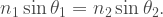
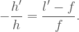
Rays 1, 2, and 3 are represented by the yellow, magenta, and cyan rays in the image, respectively. The horizontal dashed line is called the optical axis and is the axis of rotational symmetry of the lens. The vertical dashed line represents the lens plane. The black arrow is the object being imaged by the lens, and the gray arrow on the right is the image of the black arrow focused by the lens. Finally, the quantity denoted as f is the focal length, which is the distance between the lens plane and the focal point. The question we want to answer is, “How do we predict where the image forms?” Looking at the above image, we can compare four triangles formed by the rays.

This is the previous image with more stuff going on, so let’s go through what’s new. The height of the object is h, and the height of the image is h′ (read “h prime”). The distance of the object from the lens plane is l, and the distance of the image from the lens plane is l′. In short, primed distances correspond to the image, while unprimed quantities correspond to the object. There are four triangles that are color coded to help in the following discussion. Since the two yellow triangles share two angles (one right angle and a pair of vertical angles), they are similar triangles. Therefore, the ratios of the short leg to the long leg for each triangle are equal, which can be rearranged as

The negative sign is due to the fact that I’m considering h′, as drawn in the figure, to be a negative number, since it is below the axis of symmetry. By a similar argument, the purple triangles are also similar, and the ratio equality rearranges to be
Substituting the first expression into the second and doing a little more rearranging, we arrive at what’s known as the thin lens equation,

Simply put, if I know the focal length of the lens and the placement of my object, I can predict where the image will form using the reciprocal lengths shown above. This happens to work for all lenses, converging and diverging, and even for spherical mirrors, though the image is focused by reflection rather than transmission.
Now, this derivation only used rays 1 and 2 from the ray tracing rules above. To show that ray 3 is valid, I’m going to look at the tangent of the two large triangles in the image which contain the angles θ and θ′. Looking at tan θ,
Note that I used the thin lens equation and the geometric formulas above to substitute various quantities for each other, but the end result that we find is that θ and θ′ are the same! This means that the line connecting those two angles, i.e. the central ray, is undeflected through the lens!
But what happens if the object is placed within the focal length of the lens? Well, that means that 1/l is larger than 1/f, and the image distance 1/l′ is negative! The physical interpretation of a negative image distance is that the image forms on the same side of the lens that the object is sitting on. When this happens, you can’t touch the image or project it onto a wall; it lives inside the lens, similarly to how your reflection in a flat mirror lives on the other side of the mirror. You can’t touch your reflection, since you would have to go through the mirror to do so; similarly, an image with negative image distance can’t be touched since there’s a lens in the way. We call these virtual images, since you cannot touch them or project them onto a wall or screen. A virtual image always has to be viewed through the lens. An example of a virtual image is the image you see when you use a magnifying glass to zoom in on an object.
All these triangles came from working with converging, or focusing, lenses, but what if I have a diverging, or defocusing, lens? It turns out we get several triangles like before, but with one caveat: the focal length is treated as negative. This should make some intuitive sense: a positive focal length positively focuses light, and a negative focal length negatively focuses, or defocuses, light.

Instead of parallel light rays converging on the focal point, they leave the lens appearing to originate from the focal point. When all is said and done, the thin lens equation emerges, exactly as before, so long as you keep track of negative quantities. What’s interesting about diverging lenses is that the image they form is always virtual, no matter where you place the object. Mathematically, this is due to l always being positive and f always being negative. So, you can never project an image with a diverging lens alone.
An everyday application of this equation is in prescription eyeglasses. If you happen to be nearsighted, your eyeglass prescription is for diverging lenses; nearsighted eyes have too powerful a lens (too short a focal length), so the lenses used to correct them have to weaken the focusing power of the eye. Conversely, farsightedness is treated with converging lenses; such eyes need a boost in focusing power.
Finally, I want to leave you with a curious coincidence. If you have a curved mirror that is carved from a large sphere, you can construct ray diagrams similarly to how we constructed the lens ray diagrams. The only difference is that where the rays end up is determined by the Law of Reflection instead of Snell’s Law. If you assume that rays hit the mirror nearly face-on, the rules for ray tracing for curved mirrors are
- Rays incident on the mirror parallel to its axis of symmetry converge on the focal point of the mirror, which lies at half the mirror’s radius of curvature.
- Rays incident on the mirror from the focal point emerge parallel to the axis of symmetry. (This is the reverse process of rule 1.)
- Rays that go through center of curvature of the mirror reflect back the way they entered.
Visually, these rays look like this:

If you play the similar triangles game that we played with lenses, you end up getting the mirror equation,

which is identical to the thin lens equation! This allows telescopes, for instance, to use mirrors instead of lenses as the focusing elements to form images. To mathematically predict where diverging mirrors form images, simply use negative focal lengths, just like with lenses.
I hope I’ve laid out a nice foundation here, from which one could build the tools to understand cameras, film, telescopes, microscopes, and many other tools we have used not only to explore the vast reaches and smallest microcosms of the universe, but also the basis for the visual entertainment industry to record its productions. May it help you appreciate that small little lens on the back of your phone.
-A
